

Factory making China Stay Wire Gsw Wire Galvanized Stay Wire
The shopper satisfaction is our primary focus on. We uphold a consistent level of professionalism, quality, credibility and repair for Factory making China Stay Wire Gsw Wire Galvanized Stay Wire, High-quality is factory’s everyday living , Focus on customers’ demand would be the source of organization survival and advancement, We adhere to honesty and good faith doing the job attitude, seeking forward towards your coming !
The shopper satisfaction is our primary focus on. We uphold a consistent level of professionalism, quality, credibility and repair for China Galvanized Stay Wire, Gsw Wire, Looking forward, we will keep pace with the times, continuing to create new products. With our strong research team, advanced production facilities, scientific management and top services, we will supply high quality products to our customers worldwide. We sincerely invite you to be our business partners for mutual benefits.
Details
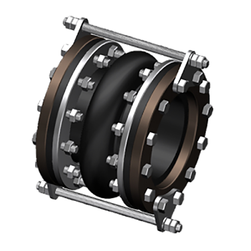
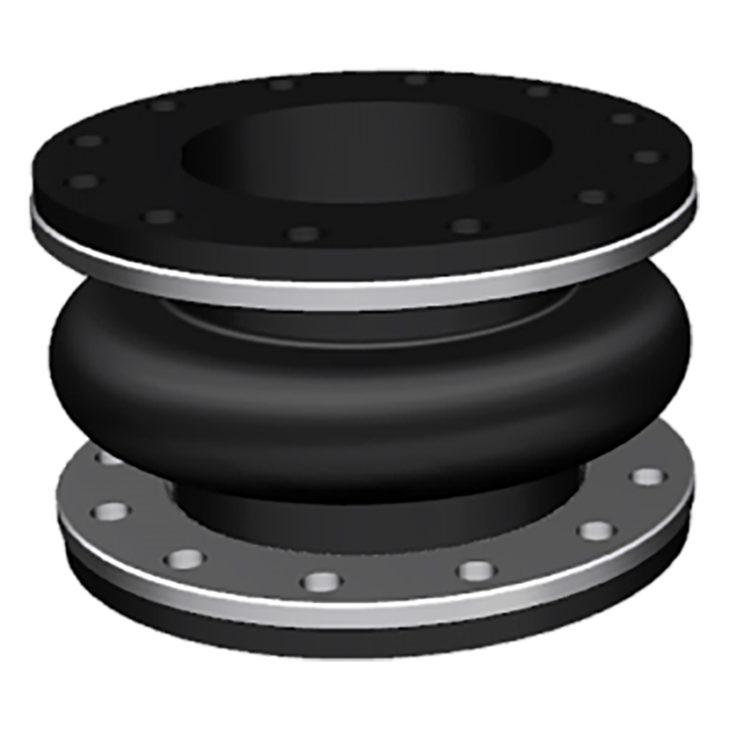
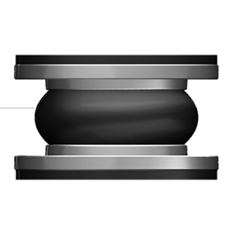
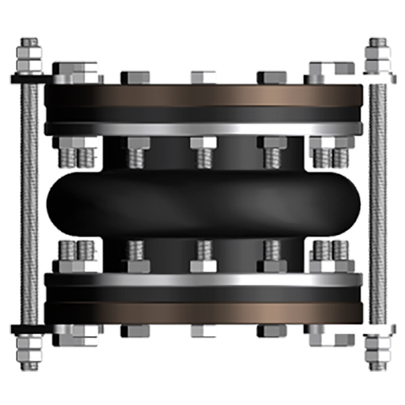
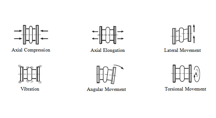
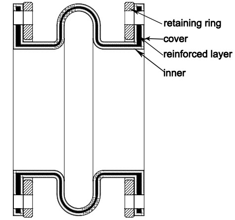
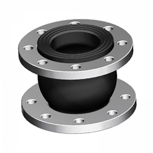
The spool type rubber joint is molded type, with a metal collar reinforced at the neck of the body. The ST stype uses a light reaining ring to support the integral flange. STF is filled arch, with 50% of the ST allowed movements, but it has 4 times spring rates than hollow arch.
| Specifications | I | II | III |
| Working Pressure Mpa (Kgf/Cm2) | 1Mpa (10) | 1.6 (16) | 2.5 (25) |
| Test Pressure | 1.5Mpa | 2.4Mpa | 3.75Mpa |
| Burst Pressure Mpa (Kgf/Cm2) | 3 (30) | 4.8 (48) | 5.5 (55) |
| Vacuum Kpa (Kgf/Cm2) | 53 (400) | 86(660) | 100 (750) |
| Materials | EPDM/NBR/SBR/NR | ||
| Diameter Range | DN15-DN600 (1/2″-24″) | ||
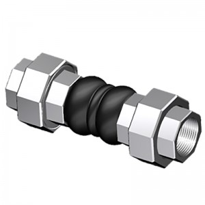
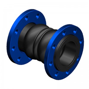
| Connection Method | FLANGETHREADCLAMP | ||
| Flanges Dimensions | DIN, EN,ANSI, BS, JIS and other standards | ||
| Applicable Medium | Air, compressed air, water, seawater, hot water, oil, acid, alkali etc. | ||
| Loading Port: | Qingdao, China | ||
| Shipment Terms: | FOB, CFR, CIF | ||
| Production Capacity: | 50000 set | ||
| Payment Terms: | L/C, T/T, D/P | ||
| Connection: | Flange, Thread | ||
| Flange Material: | Carbon Steel, Stainless Steel | ||
| Period of Delivery | about 21 working days | ||
|
SPOOL TYPE (ST) -American Standard ST |
||||||||||
|
Dimensions |
Movement Distance |
Operating Condition |
||||||||
|
Pipe Size |
O’all Length |
Flange OD |
Retaining Ring Thickness |
Axial Compression |
Axial Extension |
Lateral Deflection |
Angular Deflection |
Max w.p. (psi)-3,-4 |
Max Vacuum (in. of Hg)-5 |
|
|
Inch |
mm |
Inch |
Inch |
Inch |
Inch |
Inch |
Inch |
|||
|
2″ |
50 |
6″ |
6″ |
3/8″ |
7/16″ |
1/4″ |
±1/2″ |
19° |
150 |
26 |
|
2 1/2″ |
65 |
6″ |
7″ |
3/8″ |
7/16″ |
1/4″ |
±1/2″ |
15° |
150 |
26 |
|
3″ |
80 |
6″ |
7 1/2″ |
3/8″ |
7/16″ |
1/4″ |
±1/2″ |
13° |
150 |
26 |
|
4″ |
100 |
6″ |
9″ |
3/8″ |
7/16″ |
1/4″ |
±1/2″ |
10° |
150 |
26 |
|
5″ |
125 |
6″ |
10″ |
3/8″ |
7/16″ |
1/4″ |
±1/2″ |
8° |
150 |
26 |
|
6″ |
150 |
6″ |
11″ |
3/8″ |
7/16″ |
1/4″ |
±1/2″ |
6° |
150 |
26 |
|
8″ |
200 |
6″ |
13 1/2″ |
3/8″ |
11/16″ |
3/8″ |
±1/2″ |
6° |
150 |
26 |
|
10″ |
250 |
8″ |
16″ |
3/8″ |
11/16″ |
3/8″ |
±1/2″ |
5° |
150 |
26 |
|
12″ |
300 |
8″ |
19″ |
3/8″ |
11/16″ |
3/8″ |
±1/2″ |
5° |
150 |
26 |
|
14″ |
350 |
8″ |
21″ |
3/8″ |
11/16″ |
3/8″ |
±1/2″ |
4° |
150 |
15 |
|
16″ |
400 |
8″ |
23 1/2″ |
3/8″ |
11/16″ |
3/8″ |
±1/2″ |
4° |
150 |
15 |
|
18″ |
450 |
8″ |
25″ |
3/8″ |
11/16″ |
3/8″ |
±1/2″ |
3° |
150 |
15 |
|
20″ |
500 |
8″ |
27 1/2″ |
3/8″ |
13/16″ |
7/16″ |
±1/2″ |
3° |
150 |
15 |
|
24″ |
600 |
10″ |
32″ |
3/8″ |
13/16″ |
7/16″ |
±1/2″ |
3° |
150 |
15 |
|
SPOOL TYPE: FILLED ARCH (STF) -American Standard STF |
||||||||||
|
Dimensions |
Movement Distance |
Operating Condition |
||||||||
|
Pipe Size |
O’all Length |
Flange OD |
Retaining Ring Thickness |
Axial Compression |
Axial Extension |
Lateral Deflection |
Angular Deflection |
Max w.p. (psi)-3,-4 |
Max Vacuum (in. of Hg)-5 |
|
|
Inch |
mm |
Inch |
Inch |
Inch |
Inch |
Inch |
Inch |
|||
|
2″ |
50 |
6″ |
6″ |
3/8″ |
7/32″ |
1/8″ |
±1/4″ |
9.5° |
150 |
26 |
|
2 1/2″ |
65 |
6″ |
7″ |
3/8″ |
7/32″ |
1/8″ |
±1/4″ |
7.5° |
150 |
26 |
|
3″ |
80 |
6″ |
7 1/2″ |
3/8″ |
7/32″ |
1/8″ |
±1/4″ |
6.5° |
150 |
26 |
|
4″ |
100 |
6″ |
9″ |
3/8″ |
7/32″ |
1/8″ |
±1/4″ |
5° |
150 |
26 |
|
5″ |
125 |
6″ |
10″ |
3/8″ |
7/32″ |
1/8″ |
±1/4″ |
4° |
150 |
26 |
|
6″ |
150 |
6″ |
11″ |
3/8″ |
7/32″ |
1/8″ |
±1/4″ |
3° |
150 |
26 |
|
8″ |
200 |
6″ |
13 1/2″ |
3/8″ |
11/32″ |
3/16″ |
±1/4″ |
3° |
150 |
26 |
|
10″ |
250 |
8″ |
16″ |
3/8″ |
11/32″ |
3/16″ |
±1/4″ |
2.5° |
150 |
26 |
|
12″ |
300 |
8″ |
19″ |
3/8″ |
11/32″ |
3/16″ |
±1/4″ |
2.5° |
150 |
26 |
|
14″ |
350 |
8″ |
21″ |
3/8″ |
11/32″ |
3/16″ |
±1/4″ |
2° |
150 |
15 |
|
16″ |
400 |
8″ |
23 1/2″ |
3/8″ |
11/32″ |
3/16″ |
±1/4″ |
2° |
150 |
15 |
|
18″ |
450 |
8″ |
25″ |
3/8″ |
11/32″ |
3/16″ |
±1/4″ |
1.5° |
150 |
15 |
|
20″ |
500 |
8″ |
27 1/2″ |
3/8″ |
13/32″ |
7/32″ |
±1/4″ |
1.5° |
150 |
15 |
|
24″ |
600 |
10″ |
32″ |
3/8″ |
13/32″ |
7/32″ |
±1/4″ |
1.5° |
150 |
15 |
Products categories
-

New Arrival China China Double Sphere Flexible ...
-
Chinese Professional China Threaded Srewed Unio...
-
Wholesale Price China China Flanged Rubber Join...
-
Reliable Supplier China Zzbihe Brand Flexible S...
-
One of Hottest for China 300lbs Forged Carbon&#...
-

Discount Price China Hand-Made Spool Type Flang...
-

Phone
-

E-mail
-

Whatsapp
whatsapp

-

WeChat
Jessy Lin

-
WeChat
Ellen Zhang


